Hi,
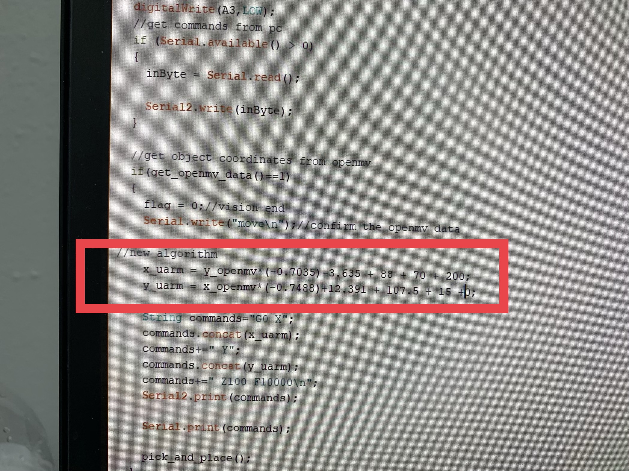
I am working on color detection and suction sample code which is on github. Although code works , uArm cannot do suction of rectangle red cube because of wrong positioning. What is the ratio between (bolb.cx and bolb.cy) and uArm x and y coordinates. As in the image i attached is openmv color detection code, I did not understand the algorithm between openmv and uarm coordinates. Are there any calibration algorithm ?
Thank you
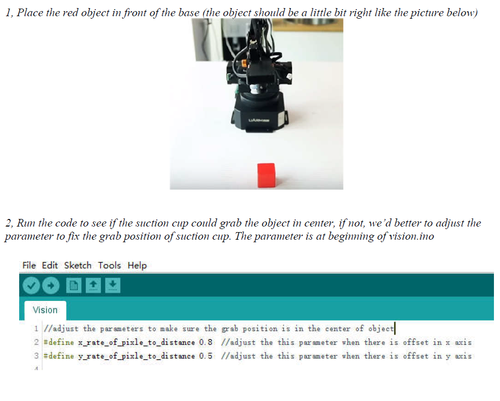
I downloaded vision.ino from github/TonyLeheng. But in my vision.ino code, there is no rate of parameter values to adjust. I think the code was updated already.
Physically adjusting the camera is an unacceptable solution.
For example if I want to find the blobs to get centroid X, Y and the rotation of a fairly large object directly under the suction cup. Moving the camera back and forth would result in incorrect positioning unless we are able to calibrate the values in vision.ino.
Your extensive use of so called “magic numbers” makes this program quite ridiculous to calibrate.
What is this supposed to mean?? why add 0, that does absolutely nothing. Why was the value 0.7305 picked, or any of the values for that manner. Why subtract a number then add 3 numbers seperately?
it is my opinion that this is quite an unrefined algorithm, impractical for any use than the basic red cube example
Hello, the reason why we offer the method of adjusting the camera is that the mechanical parts always have the torlerance and it’s hard to ignore them. And also we do think it’s the easist way to adjust the camera.
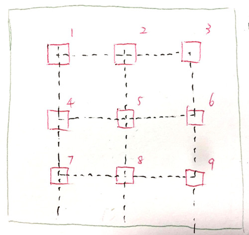
While for the magic numbers, I am so sorry for the inconvenient, I made a sketch:
As we all know, single camera would have distortion from the center to the side pixels. So we creat a method to decrease the distortion as much as possible.
The black line are the fixed position and we know the coordinates of 9 points.
The red line are the objects.
The green line is the view of camera.
Step1, setup the robot arm and move it to the initial position.
Step2, setup the camera and make sure the camera could cover the entire green area.
Step3, place the red cube from position 1-9 one by one, and write down the XY pixel data of red cube each time.
Step4, input the 9sets of data( including XY pixel, coordinates of 9 points) in the excel and get the result of coordinates trasformation.
Then we get the magic numbers.
Note: we assume that the camera is assembled flat enough so the method could work. That’s also the reason for offering the method of adjusting the camera physically.