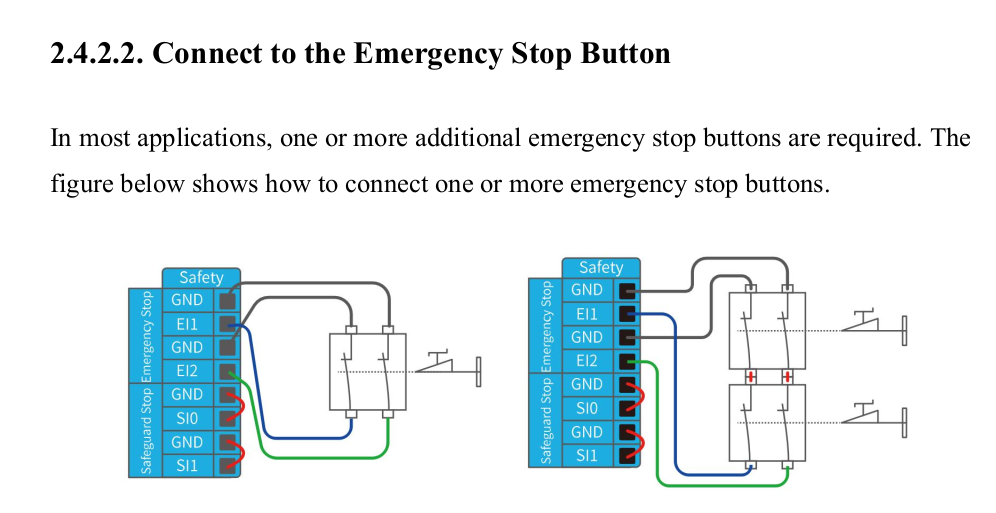
You have (Green → El2) and (Blue → El1). It should also work to have (Green → El1) and (Blue → El2) right? The second way seems a little more natural to me. I’m guessing there is some internal circuitry that checks both El1 and El2 are connected to ground.
Yes, you are right, there is internal circuitry that checks both El1 and El2 are connected to ground. Ether EI 1 or EI 2 disconnect from the GND will cut off the power of the robot.